How to assemble a computer yourself
Educational Program Technologies / / December 30, 2020
1. Prepare accessories and tools
- Case with power supply;
- motherboard;
- processor with a cooler;
- thermal paste (if it is not on the radiator);
- video card (if there is no built-in one or it does not suit you);
- memory module;
- HDD;
- keyboard;
- mouse;
- monitor;
- screwdriver;
- plastic ties;
- degreaser;
- napkin.
2. Prepare the enclosure
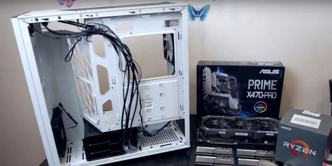
Unpack and remove the case of the system unit from the box. Use your hands or a screwdriver to unscrew the fixing screws on the rear wall and remove both side covers. Set them aside.
Most chassis are versatile and support multiple motherboard form factors, from full-size ATX to mini-ITX. Compatibility is ensured by swapping the double-sided screw rails that secure the board to the chassis.

Try on the board carefully. Align the connector panel with the cutout on the back panel and the mounting holes on the board and case. Screw in the guides at least 6-8 points around the perimeter and center of the part.
Never attach the motherboard directly to the chassis without using the rails, as this can cause a short circuit and damage the electronic components.
The required double-sided screws are necessarily included and can even be pre-installed. In this case, check to see if they match the holes on the board and re-arrange if necessary.
Reading now🔥
- How to drain water from a water heater
3. Install the power supply

If the case is equipped with a built-in power supply unit (PSU), go to the next step.
Some system units are supplied without a power supply. In such cases, the part must be purchased separately and installed at the beginning of assembly, until others interfere. accessories. As a rule, a compartment is allocated for this at the very bottom or top.
Slide the power supply back into the chassis and straighten the cables. Using a screwdriver, secure the part with four screws from the back panel. Pay attention to the position of the PSU fan: it should point downward, regardless of the bay in which it is installed.
On modular PSUs with removable cables, it makes sense to immediately connect the necessary wires and remove the excess ones, since after installation it is difficult to see the markings of the slots on the unit case.
4. Supply drives
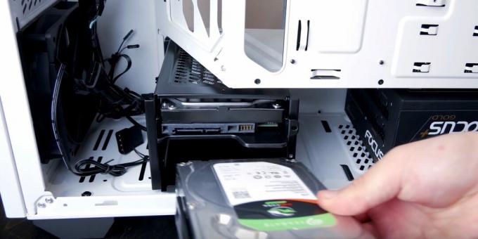
For the installation of hard disks and SSD-drives, there are special compartments in the case, usually with removable sleds for easy access. Depending on the design of the case, the location of these places is slightly different, so look for detailed information in the instructions for the system unit.
Place the hard drive in the 3.5 ”bay and secure with four screws, two on each side. Sometimes soft washers or inserts are used to reduce noise and vibration. If there are any, do not forget to put them.
SSDs can be mounted either next to hard drives in a 2.5-inch bay, or separately (on a chassis next to the motherboard or on the bottom wall). Usually, SSD first, it is screwed to a special slide, and then this part is installed in its place.
5. Place the processor in the slot
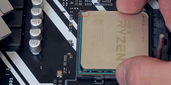
Now put the case aside for a while and start installing the motherboard components. The first step is to place the processor in a special socket called a socket. The point is simple: open the latch, insert the chip and close it. However, depending on the platform, the steps are slightly different.
Intel processors have multiple pins that touch the socket pins. At AMD, the opposite is true: the chips are dotted with pins-needles that go into the holes of the socket. To prevent the processor from being inserted incorrectly, keys are used - special cutouts on the sides or a triangle on one of the corners.
For details on installation, see the instructions for the motherboard. In general terms, you need to do the following. Pull back the socket latch to release the latch. Lift the hold-down bezel and place the chip on the contact pad using the keys. Slightly wiggle the processor and make sure it is level. Lower the frame lightly and snap the catch.
6. Secure the CPU cooler
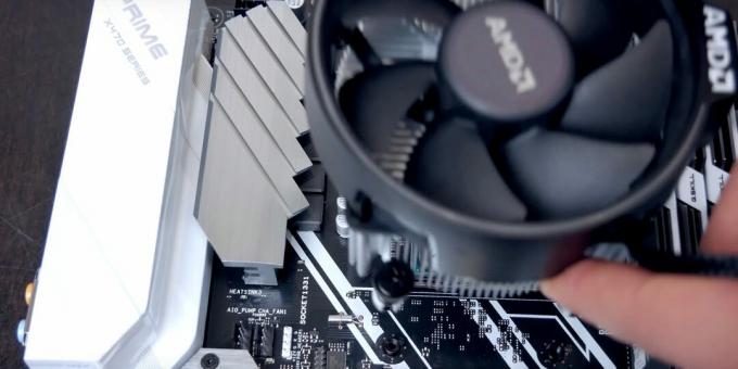
Next, a heatsink with a fan is installed on the processor. They can either come with a processor (usually simpler versions) or be purchased separately (effective solutions for productive systems).
Clean the processor cover with a cloth dampened with degreaser and apply a small amount of thermal paste to the surface. Spread the mixture evenly in a thin layer using a plastic card or with your finger wrapped in a plastic bag. Complete coolers usually already have thermal paste.
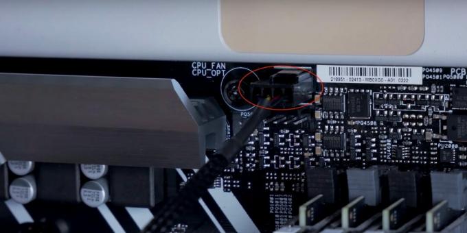
Place the heatsink on the processor and secure. Depending on the model of the cooler, the fasteners can be latches with a clamp, rotary latches, or screws that are screwed through a metal plate on the back of the motherboard. Connect the fan cable to the connector labeled CPU_FAN.
If a large cooler with a massive radiator is used, then it is better to mount it after installing the motherboard in the case. Otherwise, it will be difficult to put it in place.
7. Insert RAM

RAM is the last detail that is more convenient to insert into the motherboard before installing it in the system unit. The special slots prevent the memory modules from being inserted incorrectly.
Press the latches on the edges of the slots and slide them out to the sides. Focusing on the slots, install the memory strips into the slots and press lightly until they click. Make sure the modules are fully inserted and the side latches are closed.
If there is only one memory module, it can be installed in any slot. If two RAM strips of the same volume are used, they should be placed not side by side, but through one slot, that is, in the first and third or in the second and fourth. This will enable dual channel memory operation and will increase productivity by 10-20%.
8. Install the motherboard into the case
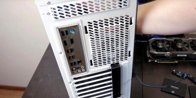
First of all, take the complete metal cover that covers the connectors and insert it into the cutout on the back of the case.
Place the board inward, sliding it against the installed metal panel so that the perforations line up with all the connectors. Align the mounting holes with the rails screwed into the chassis and use a screwdriver to tighten all the screws. Do not overdo it with the clip to avoid damaging the board.
9. Put the graphics card

If you are using integrated graphics and do not plan to install a discrete video adapter, proceed to the next step.
Video card usually has a large size and is not only inserted into its slot, but also additionally attached to the body. That is why it is installed last. For connection, a PCI Express slot is used, which is located immediately below the processor socket.
Try on a component and remove one or more blanks on the back of the system unit to provide access to the graphics adapter connectors.
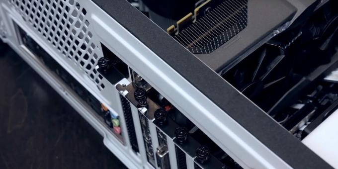
Pull the graphics card slot release and gently insert the adapter until you hear a click. Make sure the component is fully seated in the connector and attach it with one or two screws to the back of the case.
10. Connect power and other cables
When all the components are installed, it remains to connect the drives, power and other wires. Each of them has a specific connector with a key, so it is simply impossible to make a mistake and insert them incorrectly.
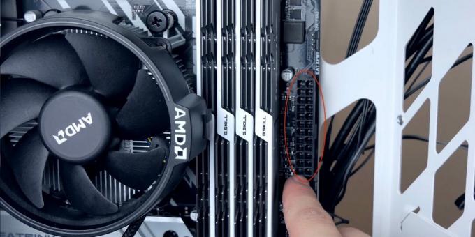
The longest 24-pin plug from the power supply connects to the corresponding connector on the motherboard. Some card models use 20-pin connectors. In this case, simply plug in the plug by sliding it to the side, or remove the additional 4-pin connector from it, if possible.
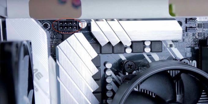
One or two 4-pin connectors provide additional power to the processor. The corresponding connectors are next to it.
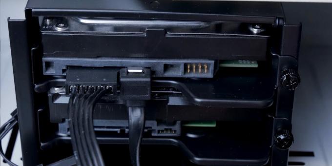
Hard drives and SSD-drives are connected by SATA cables to the motherboard and a flat 4-pin connector to the power supply.

If the video adapter has additional power connectors, connect them with the appropriate wires. These are usually 6 or 8 pin plugs, although there are various combinations: 6 + 6, 6 + 8, 8 + 8.
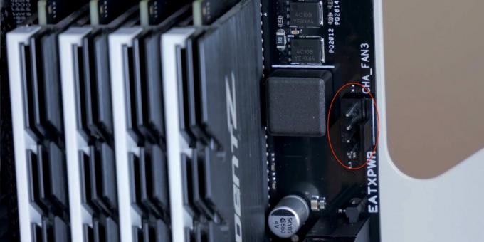
Case fans connect to three or four-pin headers on the motherboard, which are labeled CHA_FAN1, CHA_FAN2, and so on. A fan with three wires can be connected to a 4-pin connector - in this case one of the contacts will simply remain unused.
11. Connect the front panel wires
The final touch will be to connect the front panel cables, which are responsible for the operation of the power and reset buttons, LED indicators, and USB and audio connectors. In order not to get confused, see the instructions for the motherboard.
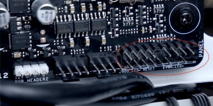
The hardest part is the buttons and indicators. They are connected with thin 2-pin plugs with the signatures RESET, HDD_LED–, PWR_LED + and so on. Connect them to the PANEL, which has the same pins. The system speaker wire is also connected here.
An arrow is sometimes used instead of a plus sign to indicate a positive lead. But, even if you confuse it, nothing terrible will happen: the LED will simply not work. For buttons, polarity is not at all important.
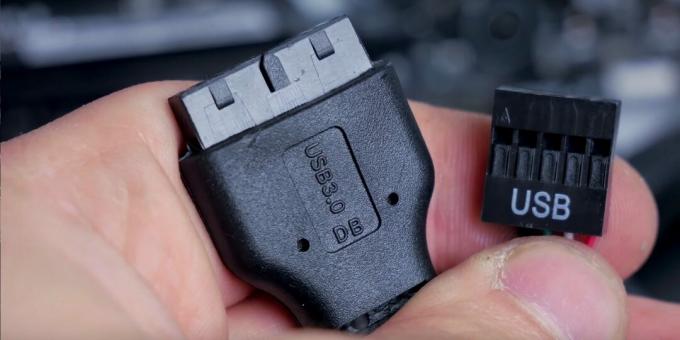
The USB port wires are connected to the corresponding connectors on the motherboard - F_USB 2.0 and F_USB 3.0. The first is smaller, the second is larger.
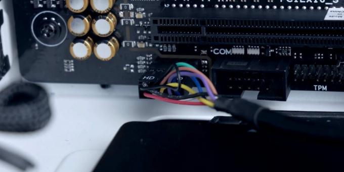
To operate the microphone and headphone jacks on the front panel, you need to connect the HD_AUDIO or AAFP plug to the same-name connector on the board.
12. Make a test run

After everything is connected, carefully inspect all connections and make sure they are reliable. Plug the power cord into a power outlet, connect monitor, keyboard, mouse, and test run the computer.
If, after pressing the power button, a single beep sounds and the setup screen opens on the monitor, then everything was done correctly. Disconnect the PC from the power supply, tie all cables inside the case with plastic ties and close the side covers.
Now you can start installing the operating system and use your new computer.
A detailed computer assembly process is shown in this video.
Read also💻🖥🔌
- How to reset BIOS and reanimate your computer
- What to do if the monitor won't turn on
- What to do if Windows won't start
- How to clean your laptop from dust
- What the BIOS signals mean


